
Connect an X3BIO biometric reader
- Before you start
- Number of turnstiles × 2 + 1 X3BIO readers; a RUT200 per reader or shared RUT956 routers; power each reader via a compatible PoE injector or +VDCIN/GND.
- Where to find it
- X3BIO readers at the entry and exit of each turnstile and at the guard station
On this page
Quick answer
Plan for number of turnstiles × 2 + 1 biometric readers: one X3BIO each for entry and exit, plus one additional reader for enrolment at the guard station. With two turnstiles, this means five readers and five PoE injectors if all readers use PoE. Connect each reader through its own injector to a RUT200, or connect several readers to a shared RUT956. Alternatively, power the X3BIO via +VDCIN and GND; a network connection is still required.
Step 1: Plan readers and equipment
Allocate two X3BIO readers to each turnstile: one for entry and one for exit. Allow for one additional X3BIO at the guard station for fingerprint enrolment.
Number of biometric readers = number of turnstiles × 2 + 1
| Turnstiles | Entry readers | Exit readers | Guard station reader | Total readers | PoE injectors when all readers use PoE |
|---|---|---|---|---|---|
| 1 | 1 | 1 | 1 | 3 | 3 |
| 2 | 2 | 2 | 1 | 5 | 5 |
| 3 | 3 | 3 | 1 | 7 | 7 |
For the example with two turnstiles, you need:
- 5 × X3BIO: four readers at the turnstiles and one at the guard station.
- 5 × compatible PoE injectors if all five readers are powered via PoE.
- 5 × RUT200 if every reader has its own router. With RUT956 routers, several readers can share a router.
- Ethernet cables to connect routers, injectors and readers, plus the respective power supplies for the routers and injectors.
When using a direct DC supply, the corresponding X3BIO does not need a PoE injector. Instead, you need a DC power supply suitable for the X3BIO version in use.
Step 2: Identify the X3BIO connectors
Locate the connectors using the following diagram.
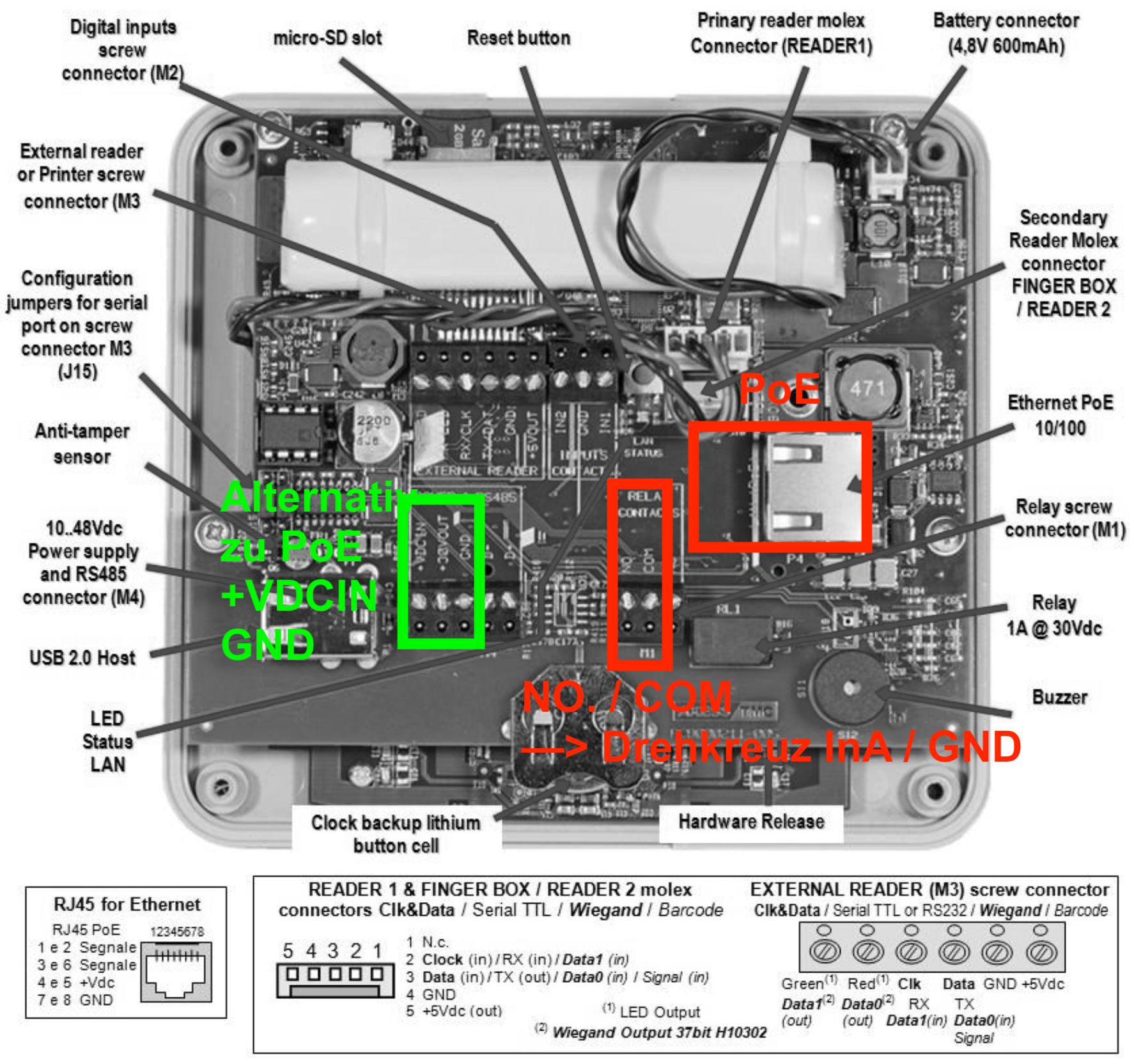
The green German annotation means “alternative to PoE: +VDCIN / GND”. The red annotation at the bottom shows the connection to the turnstile (“Drehkreuz”).
| X3BIO connector | Purpose |
|---|---|
| Ethernet / PoE (RJ45) | Network connection and, when using PoE, power supply |
| +VDCIN and GND on M4 | Alternative power supply from a DC power supply unit |
| NO and COM on M1 | Relay contacts to release the turnstile |
Step 3: Connect the network and power supply
Option A: One RUT200 and one PoE injector per reader
Connect one RUT200 and one X3BIO to each PoE injector:
- Connect a LAN port on the RUT200 to the injector’s data input, often labelled LAN or Data In.
- Connect the injector’s PoE output to the Ethernet PoE socket on the X3BIO.
- Connect the power supply specified for the injector, and power the RUT200 through its own power connector.
Connection path: RUT200 (LAN) → PoE injector (data input → PoE output) → X3BIO (Ethernet/PoE).
Use a PoE injector compatible with the X3BIO version in use. In this setup, the PoE output powers the X3BIO; the router connects to the injector’s data side. According to the RUT200 manufacturer’s specifications, its passive PoE input is not compatible with IEEE 802.3af/at/bt.
Option B: Connect several readers to a RUT956
You can connect several X3BIO readers to a RUT956 using its available LAN ports. For each reader, connect a LAN port to its injector’s data input, then connect the injector’s PoE output to that X3BIO.
For each reader: RUT956 (LAN) → dedicated PoE injector → X3BIO.
Sharing a router reduces the number of routers required. When using PoE, each reader still needs its own injector – five readers therefore still require five injectors. The number of readers you can connect directly depends on the available ports usable as LAN ports. The RUT956 has three LAN ports and one WAN port configurable as LAN, according to the manufacturer’s overview, so all five readers cannot connect directly to a single RUT956.
Option C: Power the X3BIO without PoE
Alternatively, power the X3BIO using the M4 terminals marked in green in the diagram:
- Connect the positive terminal of the compatible DC power supply to +VDCIN.
- Connect the power supply’s negative terminal to GND.
- Connect the X3BIO Ethernet socket directly to a LAN port on the router for data communication.
This supply replaces the PoE injector for that reader. The router also uses a separate power supply in this setup.
Step 4: Connect the relay to the turnstile
For readers at the turnstile, connect the NO and COM relay contacts on M1 to the release input for the relevant direction of passage. The diagram shows NO / COM → InA / GND:
| X3BIO | Turnstile in the illustrated connection example |
|---|---|
| NO | InA (release input) |
| COM | GND of the release input |
Assign the entry reader to the entry direction and the exit reader to the exit direction. Use the wiring diagram for your turnstile to identify the release terminal and its label for each direction. The illustrated InA label must not be assumed to apply to both directions.
The additional reader at the guard station is used for enrolment. For this purpose, it needs network and power connections; a relay connection to the turnstile is not required.